KEMPSVILLE VOLUNTEER RESCUE SQUAD
AMBULANCE
DETAILED TECHNICAL REQUIREMENTS
$Revision: 6509 $
Table of Contents
1 Introduction
In so far as the Kempsville Volunteer Rescue Squad (KVRS) owns or desires one or more ambulances, there exists a KVRS position derived from the KVRS bylaws called the Ambulance Procurement & Disposition Coordinator (hereafter, “the Coordinator”). Per the bylaws, The Coordinator is, among other things, required to:
Develop Detailed Technical Requirements (DTRs) by compiling, at a minimum, the following:
- Federal, state, and local requirements for such apparatus, as provided by the Captain
- Budget requirements provided by the President
- Official Vehicle Uniform requirements adopted by the membership in accordance with the Logos And Uniforms Article in these bylaws
- Special configurations and options, to the extent permitted by the budget
This document, along with the documents it references, helps to fulfill those requirements.
This document should be sufficiently detailed to specify, in a vendor-independent manner, an ambulance that reproduces, to the extent possible, what KVRS has owned in the past, plus or minus any changes KVRS desires.
Be mindful that items provided as standard equipment on KVRS’s Wheeled Coach ambulances purchased between 2008 and 2017 may be assumed in this document to be provided as standard equipment from other vendors. For instance, bucket seats in the cab and intermittent windshield wipers are not enumerated as requirement items because they are now assumed to be standard.
2 Guiding principles
These requirements are derived from the following value system:
- We value meeting all legal requirements.
- We value keeping everyone safe, including crew members, patients, and others.
- We value optimizing patient care and operations.
- We value uniquely identifying ourselves and our units to incident commanders and to the public.
- We value signaling our traffic intentions to other drivers.
- We value fiscal responsibility.
3 Applicable documents & intentional abstractions
3.1 Government requirements
The following standards and regulations form a part of this specification, to the extent specified or required by law. Unless a specific issue of a standard or regulation is identified, the issue in effect, on the date the ambulance is contracted for, shall apply:
- Federal Specification for the Star-of-Life Ambulance, KKK-A-1822, U.S. General Services Administration
- Virginia Emergency Medical Services Regulations (12 VAC 5-31)
- City of Virginia Beach Department of EMS Medical Equipment And Supplies Policy
In the event of a conflict between the text of this specification and the references cited above, the text of this specification shall take precedence to the extent feasible.
3.2 Included documents
The standards and requirements contained in the latest version of the following documents are hereby included by reference:
- KVRS Ambulance Graphics Package
- Letters issued to establish official markups to the KVRS Ambulance Graphics Package not yet incorporated into the package itself
3.3 Intentional abstractions
This document intentionally does not, nor should it be modified to, directly contain any specification of:
- make, model, or class of chassis
- items that depend upon chassis selection or configuration (such as walkthrough doors for Type III’s or accordion bellows tube for Type I’s)
- dominant colors or squad-specific graphic elements
The specifications in this document should be equally applicable regardless of the squad’s choice of these items for a particular purchase order. Rather, the above kinds of specifications should be deferred to subordinate documents or purchase order line items.
4 Documentation conventions
4.1 Doors
When referring to doors in the payload module, the term entry door is used to describe doors intended for ingress/egress of personnel.
4.2 Relative location terminology
When referring to locations within a compartment, the terms left and right shall mean from the perspective of a person who is facing directly into that compartment. The terms inboard and outboard shall mean toward or away, respectively, from a line running through the center of the vehicle from its front bumper to its rear bumper.
4.3 Budget priorities
The budget priority column contains values to serve as a guideline when it is not financially feasible to implement this entire set of specifications. In particular:
| This indication... | ...means the specification is deemed to be... |
| MAY | not important enough to implement if the squad’s other funding priorities have not been met |
| SHOULD | important enough to implement if the ambulance procurement budget allows |
| MUST | so important that it would be better to secure additional funding than to not implement the specification |
5 SPECIFICATIONS
5.1 Safety
| # | Description | Rationale | Budget priority |
| 5.1.1 | Install exterior side mirrors that are remotely adjustable from the driver’s position. | To optimize visibility adjustments, even when driver-only. | MUST |
| 5.1.2 | Install heatable exterior side mirrors. | To improve cold weather visibility. | MUST |
| 5.1.3 | Install the most durable valve stems available, meeting or exceeding the TR416 rating. | Tire pressure failure attributable to failure of the valve stem has been identified as not uncommon. | MUST |
| 5.1.4 | Install most durable available rear entry door hold-open systems such that doors will open as far as possible, and such that none of the prongs are likely to be used as a step. | To prevent rear doors from swinging in stiff winds and from interfering with patient loading/unloading. To prevent premature wear. To prevent damage from abuse. | MUST |
| 5.1.5 | Install brushed aluminum panels on interior of all payload module entry doors. | Allows application of reflective chevrons. | MUST |
| 5.1.6 | Install backup alarm without a cutoff switch. | Prevents crew from defeating safety mechanism. | MUST |
| 5.1.7 | Provide for both rear load lights and the rearmost side scene lights to activate when transmission is in “Reverse”. | Increases backing illumination. | MUST |
| 5.1.8 | Install two white scene lights on each side of payload module. | Increases scene and backing illumination. | SHOULD |
| 5.1.9 | Install two white rear load lights. | Increases scene and backing illumination. | SHOULD |
| 5.1.10 | Provide for both curb-side scene lights to activate when side payload module entry door is open. | Improves visibility when exiting from side of payload module. | SHOULD |
| 5.1.11 | Install stepwell lighting in stepwell. | Improves ability to navigate steps in dark. | MUST |
| 5.1.12 | Install Squad Saver Net, 2” straps, black, at head of squad bench, attached with removable latches to floor, curb-side wall, and overhead liner. | Greater surface area than squad saver arm rest; and more likely to work when standard vehicle attitude is upset. Detachability allows tall patients to be secured supine on squad bench. | MUST |
| 5.1.13 | Provide “airway seat” with integral seat belt and integral child seat. Install so front edge of seat is 99” from closed rear doors when seat is moved all the way toward the cot. | Assures seat belt will work as engineered. Provides another option for transporting small children. Assures seat will be usable for airway management. | MUST |
| 5.1.14 | Use seamless upholstery in the payload module wherever possible. | Reduces chances of contaminants surviving decon efforts. | MUST |
| 5.1.15 | In interior over rear doors, install brake/turn indicators slaved to driver’s controls, instead of clock. | Provides payload module occupants some warning of driver intent. | SHOULD |
| 5.1.16 | Install chevrons above and to both sides of the rear doors. The stripes should alternate between the squad’s dominant color and reflective white. | Provides visual warning to the rear. | MUST |
| 5.1.17 | Install chevrons on the lower half of each rear entry door, and on the lower half of the payload module side entry door. | Provides visual warning to the rear when the doors are open. | MUST |
| 5.1.18 | Provide a Federal PA300 siren. | Extremely simple and intuitive interface that has remained the same for many years. All operations can be performed by touch. Minimizes need to look away from the road. | SHOULD |
| 5.1.19 | Install siren so that horn ring changes siren tones. | Allows driver to keep eyes on the road and both hands on the steering wheel. | MUST |
| 5.1.20 | Mount siren speakers through cutouts in front bumper if feasible. | Noticeably reduces amount of sound reflected back into ambulance cabin. | SHOULD |
| 5.1.21 | Do not provide vanity wheel covers. | Assures that actual lug nuts will be visible at all times. Eliminates need for valve stem extensions, failure of which has been identified as not uncommon. | MUST |
| 5.1.22 | Provide power windows and door locks for the cab. | Makes it faster and easier to control cab door locks from multiple positions, and makes it faster and easier to control cab windows from driver’s position. | MUST |
| 5.1.23 | Provide a tilt (and telescopic, if available) steering wheel. | Allows finer control of driving position. | SHOULD |
5.2 Patient care and operations
| # | Description | Rationale | Budget priority |
| 5.2.1 | Provide a payload module at least 170” long. | This is the minimum size adequate to carry the gear that we are accustomed to carrying. A length that also allows designated areas for carrying crew personal items, including but not limited to turnout gear, is desireable. | MUST |
| 5.2.2 | Install an additional alternator, if a factory option. | The electrical system must be capable of simultaneously powering all typically attached electrical components, with enough reserve to handle at least some atypically attached electrical components. | MUST |
| 5.2.3 | Delete any air microfiltration system if it takes up otherwise useful space. | We are not satisified that the effectiveness of these systems has been proven to the extent that it prevents disease transmission or hazmat exposure. We do not have an effective program in place for replacing microfilters on schedule, hence these systems go to waste. | SHOULD |
| 5.2.4 | Install air conditioner for the payload module of the highest capacity and highest Mean Time To Failure (MTTF) available. | Inadequacy and failure rates of air conditioning in the payload module have been frequent irritants. | MUST |
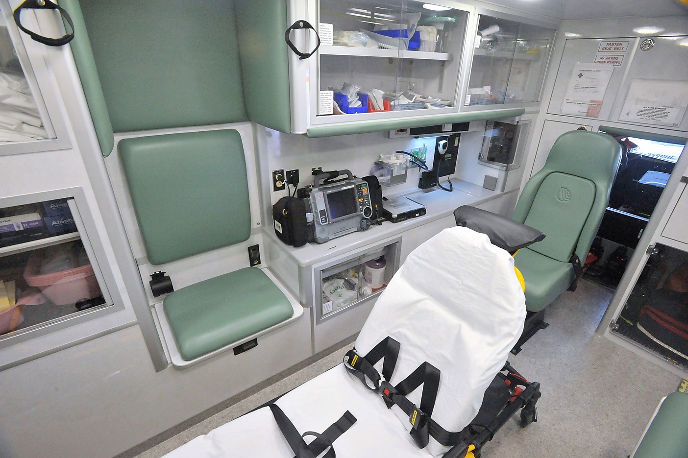
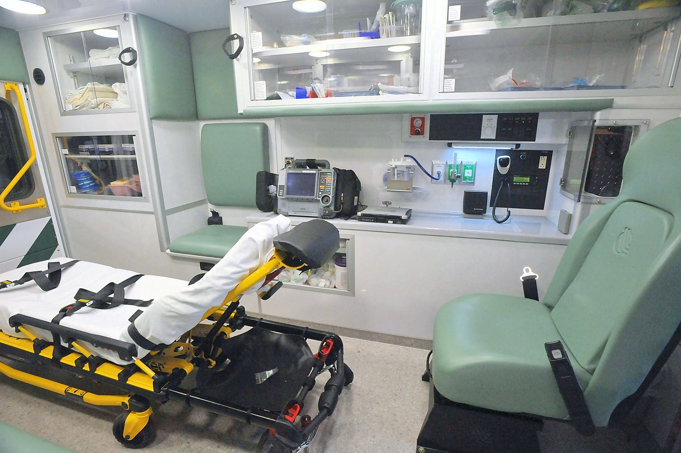
| 5.2.5 | Install “CPR seat” so that it will be adjacent to patient’s pelvis/thigh area (not adjacent to a supine patient’s chest). Delete rearward cabinets and/or rearward telemetry area, and extend action area to account for this seat placement. (See illustration section 6.1↓.) | No one sits down when doing CPR. Seat needs to be placed to optimize attendant position for starting an IV on patient’s right hand/arm. Without moving the seat to this position, the seat is so far forward that the attendant is almost sitting behind the typical patient’s field of vision. | MUST |
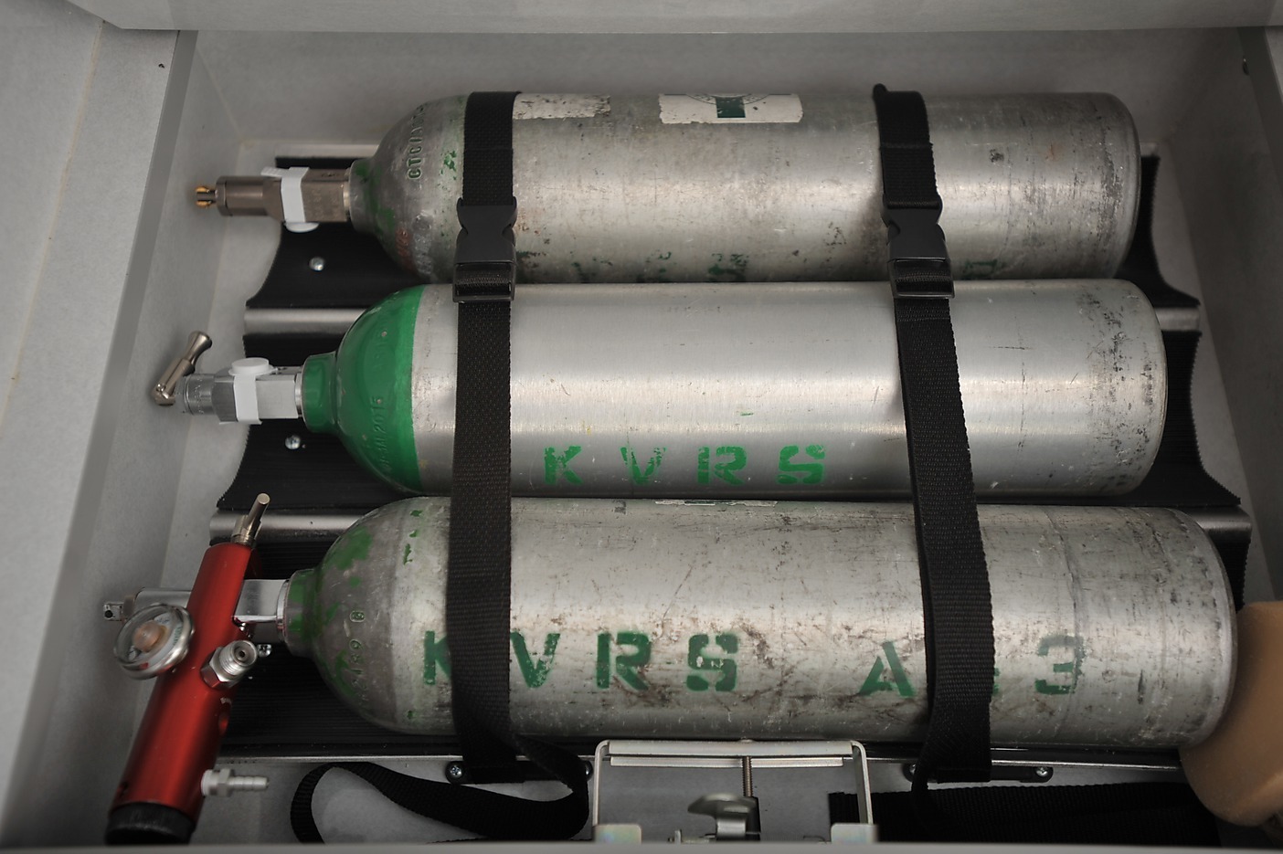
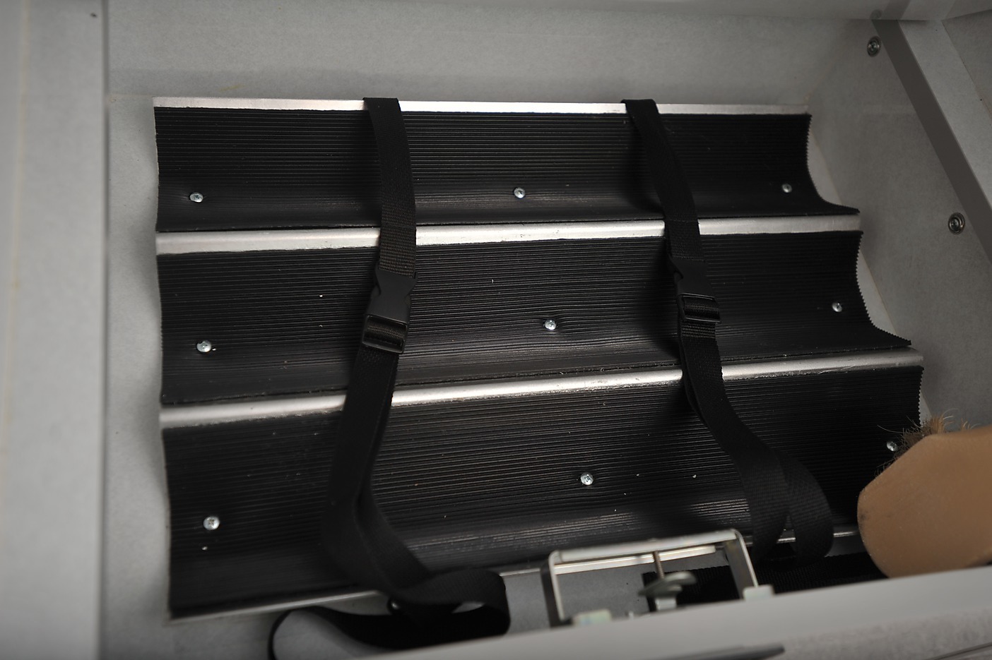
| 5.2.6 | Under “CPR seat” lid, provide sufficient storage for 3 “D” size oxygen tanks. Install a “W” trough at the bottom of the compartment. Install two quick release straps, to secure the tanks at the 1/4 and 3/4 tank length positions. Tanks are 21” long/high x 4.5” diameter. Must be able to place and remove the tanks without turning them sideways. (See illustration section 6.2↓.) | Allows for safe interior storage of additional portable oxygen. | MUST |
| 5.2.7 | Install additional “severe weather” in-wall insulation, if offered. | Assists with temperature control and sound dampening. | SHOULD |
| 5.2.8 | Apply undercoating, if offered. | Assists with temperature control, sound dampening, and corrosion resistance. | MAY |
| 5.2.9 | Provide an extended cab (but not a crew cab), if available on chassis. | Allows room for radio shop to mount radio/router equipment. May allow designated area for carrying crew personal items, including but not limited to turnout gear. | MAY |
| 5.2.10 | Provide a 3” drop skirt at outer edges of payload module forward of rear wheel. | Provides easier ingress & egress. Rampover angle is not a major concern in our district. | SHOULD |
| 5.2.11 | Provide a double step at side payload module entrance, each step equal height. | Provides easier ingress & egress. | SHOULD |
| 5.2.12 | Extend bottoms of compartments within drop-skirt area to bottom of drop-skirt. | Provides more room for gear. | SHOULD |
| 5.2.13 | Provide sweep-out compartment bottoms where feasible. | Easier to clean. | SHOULD |
| 5.2.14 | Provide a compartment (IV/DRUG COMPARTMENT) in the payload module right front cabinet that reaches ceiling level and that is dimensioned to hold at least one TEMS IV Box and one TEMS Drug Box, lockable with a standard padlock. Assume both TEMS boxes are 19” deep 10.75” high 11.5” wide. This compartment is only to be accessible from the interior, and its door must be made of a rigid material. | City requirement: “All IV and drug boxes will be stored in locked compartments or brackets when not in use. Compartment design must be approved by the Department and the Virginia Department of Health Office of EMS. A standard lock shall be used for all rescue squad, Department of EMS, and Fire Department operated vehicles.” | MUST |
| 5.2.15 | Provide a 100% height external right rearmost compartment (BACKBOARD COMPARTMENT). In this compartment, install a 3/16” thich 14” deep vertical divider 8.25” from right wall. Install a shelf forward of aforementioned vertical divider halfway between ceiling and floor, mounted on 20” of adjustable shelf track (10” of track above and below shelf). Install a seat belt across entire compartment opening, 30” down from ceiling, 2” from compartment opening, secured with zinc footman loops. (See illustration section 6.3↓.) | Allows orderly stowage of backboards and scoop stretcher, velcro splint pack, and C-collar pack. Strap helps prevent gear from falling onto personnel. | MUST |
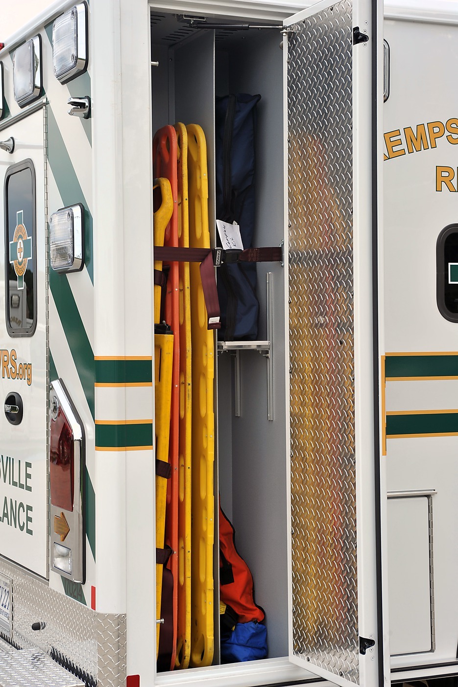
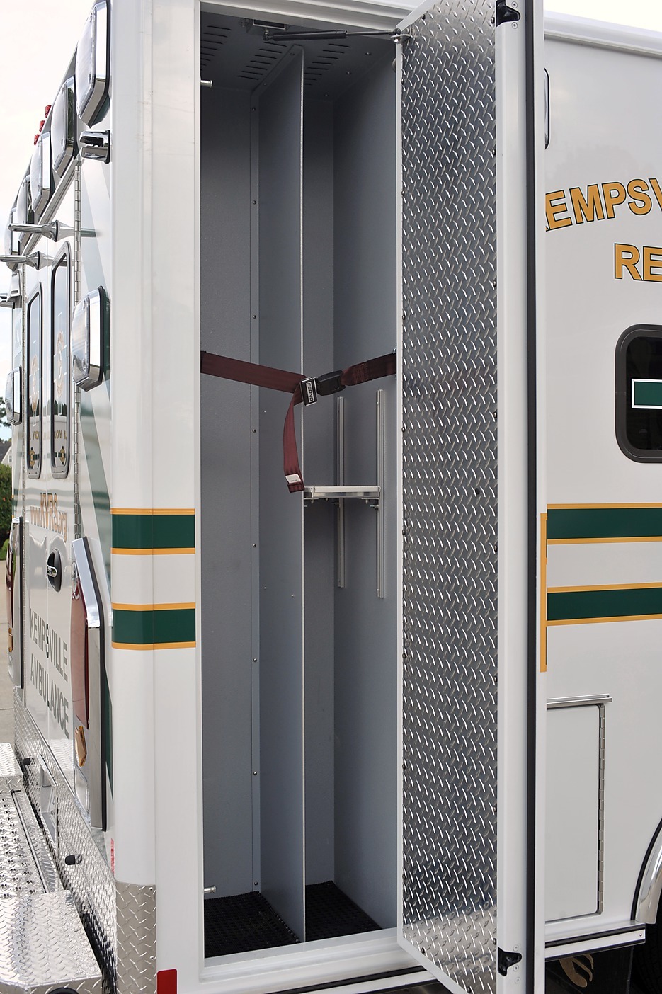
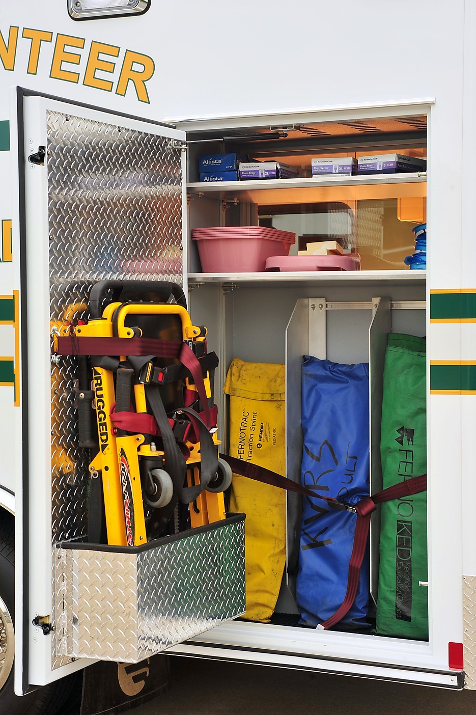
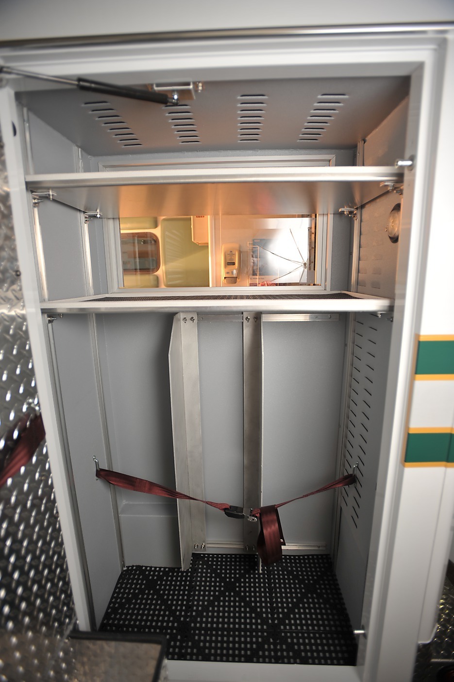
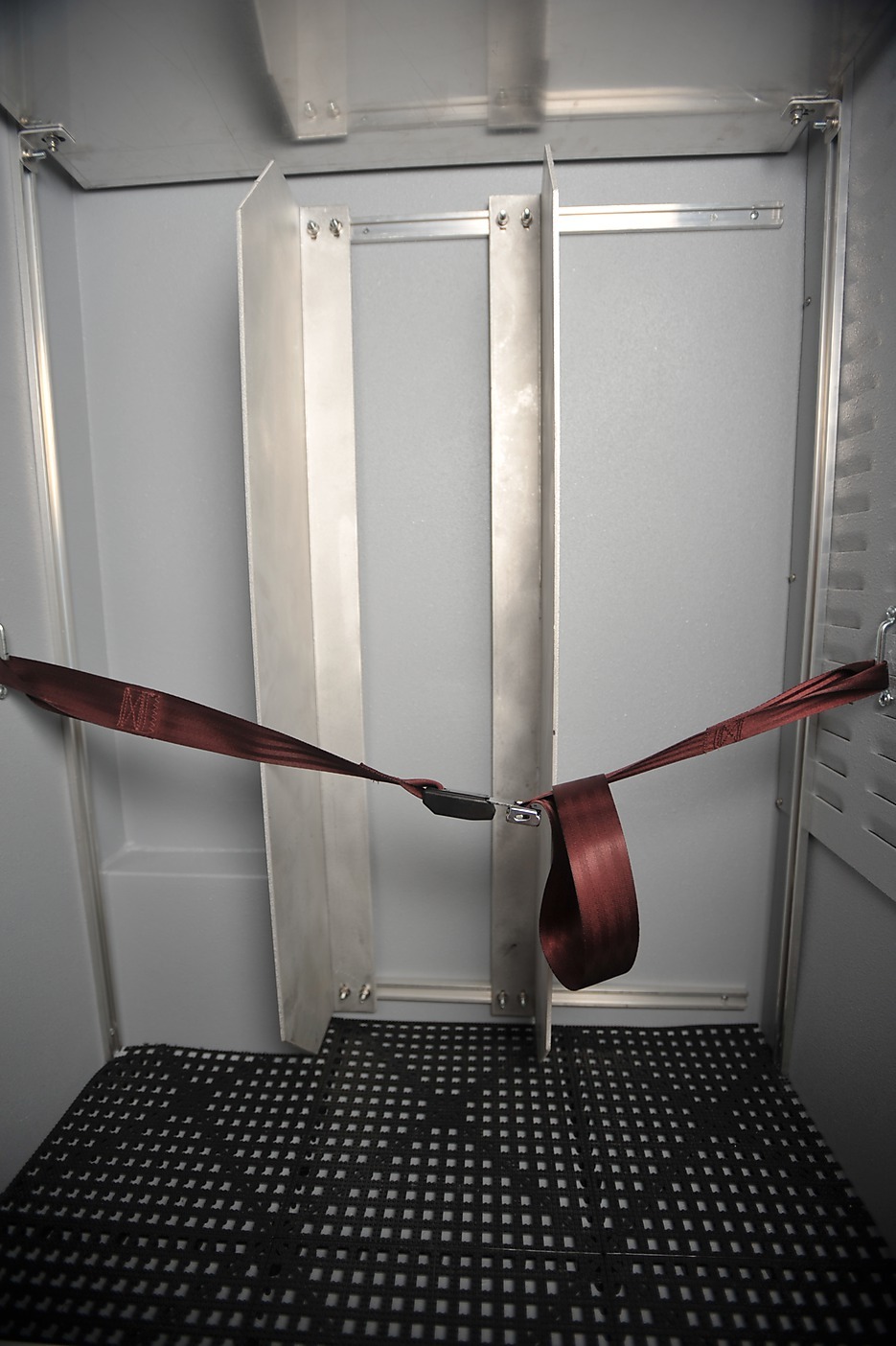
| 5.2.16 | Provide a 3/4 height external left rearmost compartment (STAIR CHAIR COMPARTMENT). Approximately 40” from floor, make this compartment accessible from interior as well. In the lower approximately 40” of this compartment, install two adjustable 3/16” thick 40” tall 7.5” deep vertical dividers on shelf track mounted to and running the width of the inboard wall, to divide the inboard section of the compartment into thirds. Install a seat belt on the left and right walls, 8” from the inboard wall, secured with zinc footman loops. In the interior-accessible upper portion of this compartment, install adjustable shelf track and two shelves. (See illustration section 6.4↓.) | Allows orderly stowage of traction splints and KEDs, and interior/exterior access to other items. Seat belts help prevent gear from falling into personnel. | MUST |
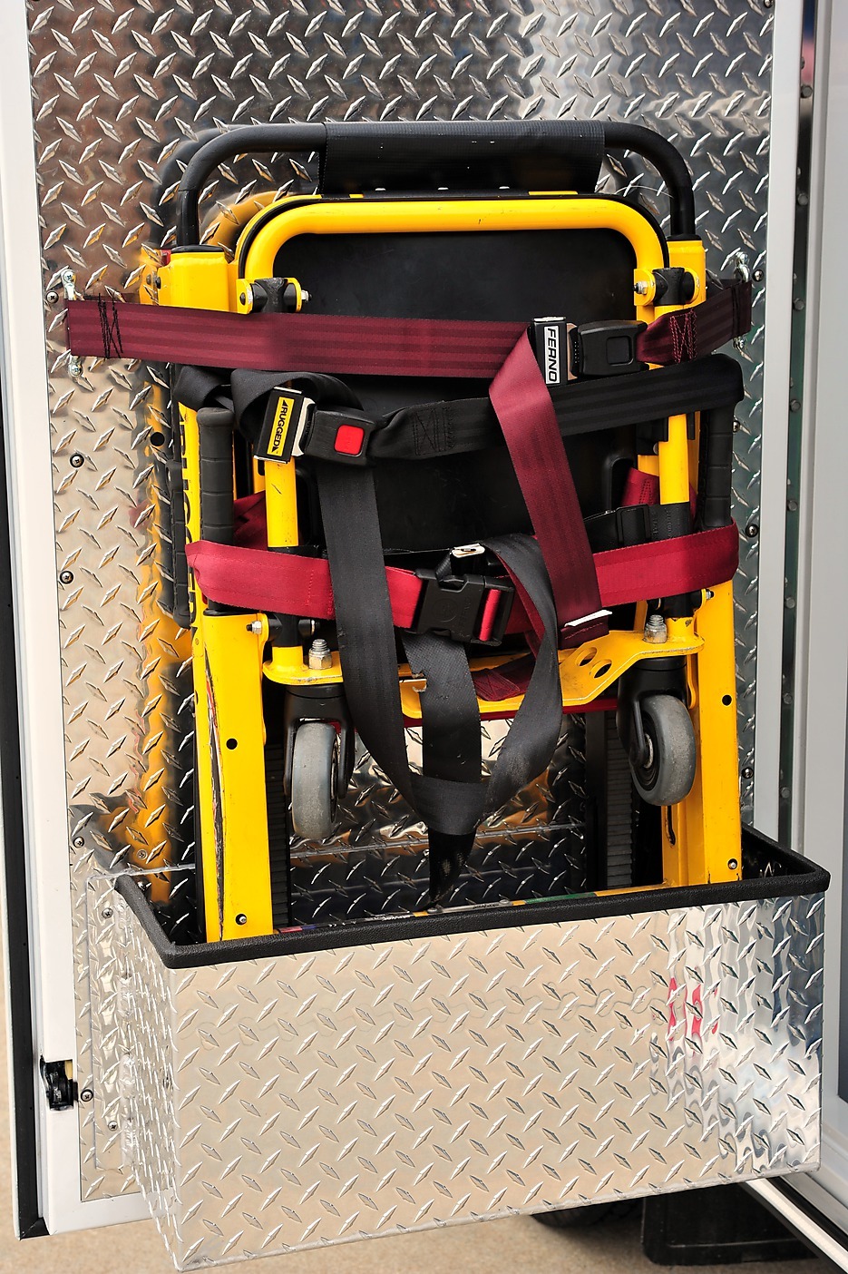
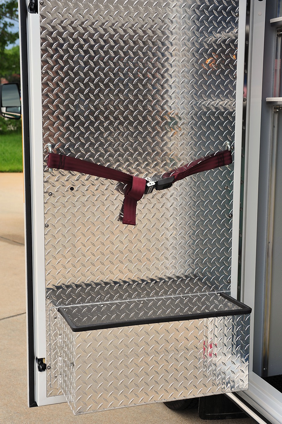
| 5.2.17 | Reinforce door/hinge of STAIR CHAIR COMPARTMENT. On interior of this door, near the bottom, mount a box sufficient to carry a 37.5” high 20.5” wide 8” deep heavy duty (Stryker 6252) stair chair. Reinforce the box with additional screws, or rivets, or internal and external continuous bead welds. Install a horizontal seat belt, secured with zinc footman loops, approximately 30” above bottom of stair chair box sufficient to secure top portion of stair chair. (See illustration section 6.5↓.) | Allows orderly stowage of stair chair and uses door rather than muscle to shift stair chair away from compartment interior. | MUST |
| 5.2.18 | Provide a 3/4 height external left forwardmost compartment (MAIN OXYGEN COMPARTMENT). The upper portion of this compartment must be accessible via a lexan door to the interior action area. | To carry main oxygen. Provides interior access to main O2 valve. | MUST |
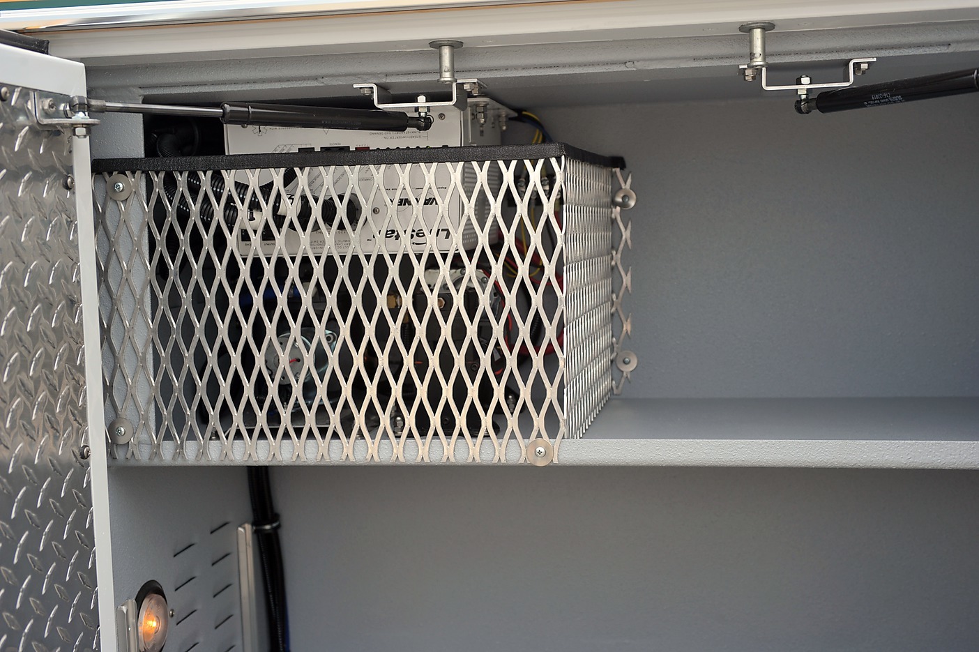
| 5.2.19 | Provide a 1/2 height external left compartment immediately behind the MAIN OXYGEN COMPARTMENT. In this compartment, mount inverter on ceiling, close to forward wall. Install a fixed shelf sufficiently below the inverter to allow the following: Mount airhorn pump and vacuum pumps to the fixed shelf so they will sit immediately below the inverter. Install a single heat isolation cage around the area occupied by the inverter, airhorn pump, and vacuum pump. (See illustration section 6.6↓.) | Allows space-efficient mounting of inverter, airhorn pump, and vacuum pump. | MUST |
| 5.2.20 | Apply privacy tinting to all payload module windows. | Patient privacy and climate control. | MUST |
| 5.2.21 | Install a grab bar inside the side payload module entry. | To allow a person to steady self using left hand while entering payload module. | SHOULD |
| 5.2.22 | Install an exterior stealth failsafe switch in passenger side grill to unlock at least as many doors as may be required to regain access to all electrically-lockable spaces. | To prevent lock-outs. | MUST |
| 5.2.23 | Provide gas strut hold-open for side payload module door. | We’ve been dissatisfied with spring hold-opens. | MUST |
| 5.2.24 | Provide for compartment doors to open 135 degrees unless doing so allows compartment door to impact travel of another door at any point. | Allows easier access to gear. | SHOULD |
| 5.2.25 | Upgrade incandescent lighting to LED wherever possible. | Reduces electrical load and burn-outs. | MUST |
| 5.2.26 | Provide for payload module main power bus to be slaved to OEM ignition switch. | Allows more intuitive control of payload module power. | MUST |
| 5.2.27 | Provide 5 minutes of electrical power to payload module (but not to payload module air conditioner blower) when ignition is switched off. Provide dual-action momentary rocker switch on driver’s side of cab console to (a) force timer to expire, and (b) reactivate timer. | Prevents sudden darkness from interfering with patient care and egress. Allows driver to conserve battery when timer is not needed. Allows driver to recover from inadvertent interference with timer function. | MUST |
| 5.2.28 | Install one extra 12V automotive battery in payload module battery compartment, wired in parallel but isolated, for use when the vehicle is not running without affecting ability to start the vehicle. | Reduces electrical and starting failures. | SHOULD |
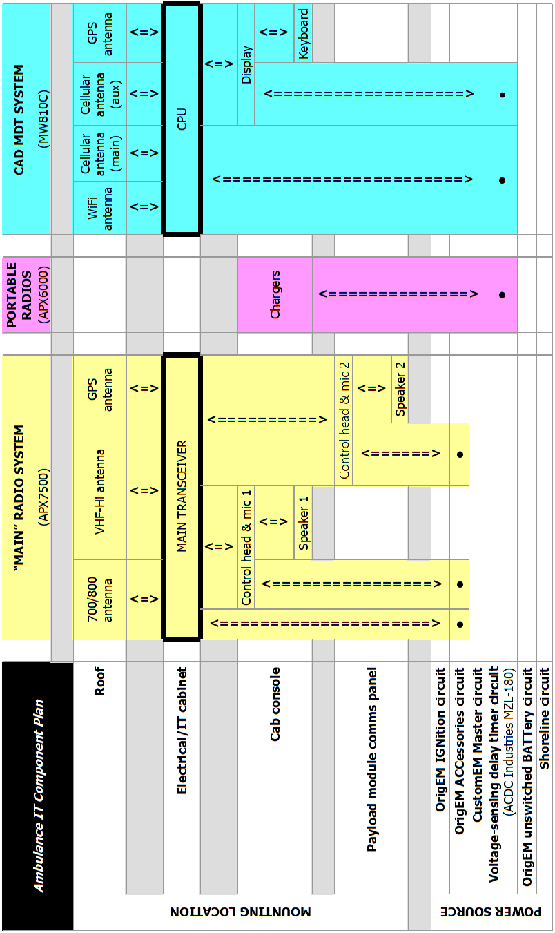
| 5.2.29 | Install ’”Main” Radio System’, ’Portable Radio’ chargers, and ’CAD MDT System’ as indicated in 6.9↓, 6.10↓, and 6.11↓, using equipment specified by the City Of Virginia Beach / Communications & Information Technology Department / Telecommunications division. | For standard complement of radios & MDT equipment. | MUST |
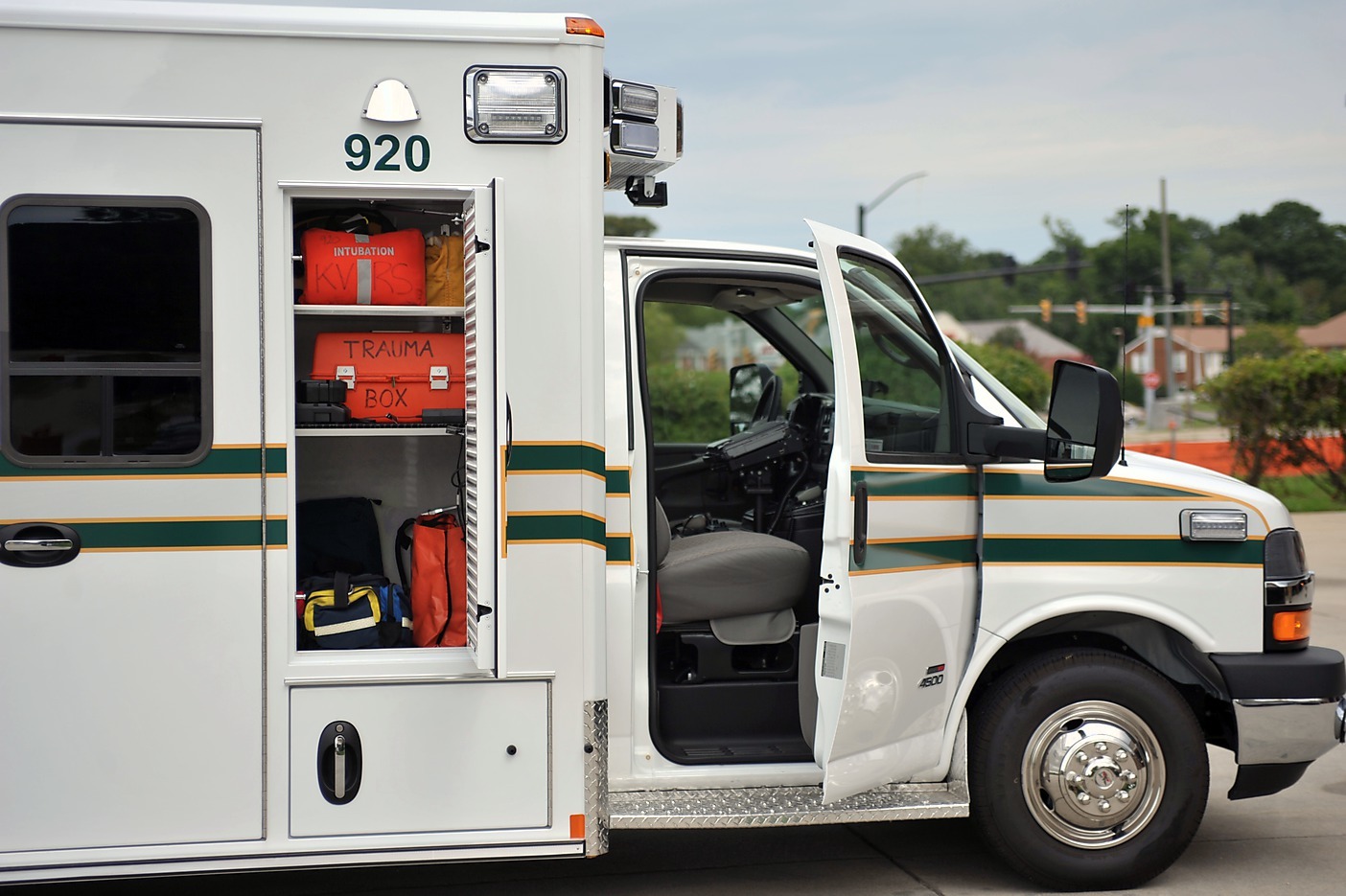
| 5.2.30 | Provide a door for exterior access to the non-lockable portion of the payload module’s right front cabinet. (See illustration section 6.7↓.) | For efficient outside access to portable equipment. | MUST |
| 5.2.31 | Provide 2 cigar lighter outlets, on 20 amp circuit, energized by ignition & shoreline, in payload module as follows: One on wall in action area adjacent to “airway seat”, the other on wall in extended action area just forward of “CPR seat”. | To power squad and personal gear. | SHOULD |
| 5.2.32 | Provide a cigar lighter outlet, on 20 AMP circuit, energized by ignition & shoreline, in payload module as follows: In right front cabinet, in the uppermost portion that is accessible from the interior and the exterior. | To charge portable gear. | MUST |
| 5.2.33 | Provide a 12VDC 15 amp power source (hot and ground) on ignition circuit w/6 ft pigtail, terminating behind the action area wall. | To power gear. | MUST |
| 5.2.34 | Provide a 12VDC 15 amp power source (hot and ground) on ignition circuit w/6 ft pigtail, terminating in the front cab console. | To power gear. | MUST |
| 5.2.35 | Provide a 12VDC 30 amp power source (hot and ground) on ignition circuit w/6 ft pigtail, terminating behind the passenger seat. | To power gear. | MUST |
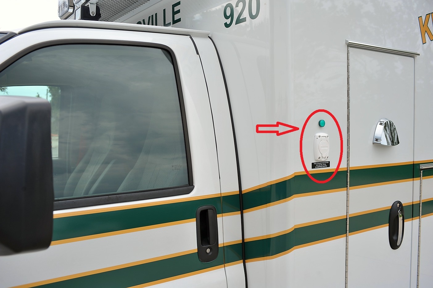
| 5.2.36 | Install auto-eject shoreline inlet, with interrupter, with white cover, on driver’s side of payload module just forward of forewardmost compartment at approximately eye level. Install a green LED 110VAC shoreline indicator light just above. (See illustration section 6.8↓.) | To make the shoreline easily accessible to the driver as driver gets in/out of driver’s seat, and to indicate whether circuit is successfully energized. Interrupter prevents sparking if under load when ejected. | MUST |
| 5.2.37 | Provide 2 dual-socket 110VAC outlets in payload module as follows: One on wall in action area adjacent to “airway seat”, the other on wall in extended action area just forward of “CPR seat”. | To power gear. | MUST |
| 5.2.38 | Provide a dual-socket 110VAC outlet in payload module as follows: In right front cabinet, in the uppermost portion that is accessible from the interior and the exterior. | To power gear. | MUST |
| 5.2.39 | Rig inverter to be “always on”. Delete action area inverter switch. | Required by our standard complement of I.T. gear. | MUST |
| 5.2.40 | If allowed by engine manufacturer, install engine block heater, with switch behind driver’s seat, wired to shoreline. | Extends engine life. | SHOULD |
| 5.2.41 | Use 1050W inverter/charger to power all 110VAC receptacles, “charger 20 amp automatic w/integral cut off”. | To power and charge gear appropriately. | MUST |
| 5.2.42 | Provide “Miami-Dade” front cab console (or similar). | Has room for our standard complement of radio heads. Allows orderly stowage of more gear. Has cup-holders. | MUST |
| 5.2.43 | Replace OEM cab domelight with domelight that can be switched to either white or red, wired to ignition, with switches on dome light itself. | Allows interior lighting with less impact on driver vision, and intuitive activation. | SHOULD |
| 5.2.44 | If using CoolBar or equivalent with angled faces, install additional white scene light on lower half of each angled face, to come on with same-side standard scene lights. | Extends scene lighting to area more forward than standard. | MAY |
| 5.2.45 | On payload module interior ceiling, install white lights, with appropriate switches in action area, as follows: 3 dual-intensity on curb side; 4 dual-intensity on street side; 3 flourescent recessed approximately on center line. | Increases illumination options for patient care. | MUST |
| 5.2.46 | Install a 5” (or so) light under cabinetry to illuminate action area only, with integral switch. | Allows limited lighting for attendant without necessarily lighting patient. | MAY |
| 5.2.47 | Install 15-minute timer switch on battery circuit on curb-side wall at front of squad bench, to allow activation & deactivation of interior overhead flourescent lights only. | To better control lighting. | MUST |
| 5.2.48 | Install small light in circuit board compartment, with integral switch, on constant hot circuit. | To assist with electrical troubleshooting. | SHOULD |
| 5.2.49 | Install approximately full-length overhead grab rail in payload module. | To assist with steadying personnel. | MUST |
| 5.2.50 | Install high-durability grab rails on payload module door interiors. | To assist with entering/exiting payload module. | MUST |
| 5.2.51 | Install rack for M or H oxygen cylinder in MAIN OXYGEN COMPARTMENT, on right wall as close to inboard wall as possible, allowing hand access to 3 ratchet-style straps. | Our oxygen replenishment system negates need to remove/replace oxygen cylinders. | MUST |
| 5.2.52 | Install Ohio-style oxygen/suction ports as follows: 2 O2 outlets and 1 vacuum port in action area; 1 O2 outlet on curb-side wall at head of squad bench. | Provides for airway & oxygenation of high acuity patient on cot, while also providing for oxygenation of lower acuity patient on squad bench. | MUST |
| 5.2.53 | Provide IV hooks only as follows: Perko style or equivalent, just below ceiling; w/velcro straps positioned to prevent IV bags from swinging; 1 on curb-side at front of squad bench; 1 on curb-side roughly midway down squad bench; 1 on street side just forward of “CPR seat”; 1 on street side just rear of “CPR seat”. | Unobtrusive, convenient, and proximity to walls helps prevent swinging even if straps aren’t utilized. | MUST |
| 5.2.54 | Install tethered oxygen wrench in MAIN OXYGEN COMPARTMENT. | MUST | |
| 5.2.55 | Use lexan interior compartment doors to the extent possible, without compromising the required rigidity of the IV/DRUG COMPARTMENT. | Allows attendants to see contents of compartment without having to open compartment. | SHOULD |
| 5.2.56 | In payload module right front cabinet, if any interior compartment doors open to the side, make sure the handle is on the left and the hinge is on the right. | Experience shows that access is hindered if doors open in other direction. | MUST |
| 5.2.57 | Provide a squad bench with a split 50/50 lid. | Allows access to gear under lid(s) even if gear or people are occupying one lid and can not be easily moved. | MUST |
| 5.2.58 | Provide gas strut (at least 30 LB capacity) hold-opens for squad bench lids. | Prevents lids from inadvertently falling and scraping/pinching personnel. | MUST |
| 5.2.59 | Use rivets to secure front & rear kickplates/stoneguards to body. | Our experience is that screws tend to back out. | MUST |
| 5.2.60 | Install dri-deck, turtletile, or equivalent, at bottom of all exterior compartments and shelves. | Allows rain to drip below gear. | SHOULD |
| 5.2.61 | Install a Stryker Power-LOAD system. | Power loading reduces likelihood of exertion-related crew injury and has member recruitment & retention value. | MAY |
| 5.2.62 | Install an ACDC Industries MZL-180 (or, upon customer approval, a functionally equivalent) voltage-sensing delay timer in the electrical/IT cabinet, and rig it to supply power to the CAD MDT System CPU. | Allows CAD MDT to receive messages while ambulance is off, unless voltage drop would risk preventing ambulance from being started. | MUST |
| 5.2.63 | Do not install anything at front of squad bench that would interfere with securing a tall patient supine on the squad bench – unless also providing a quick-release mechanism to allow removal of the interfering object. | Allows crew to secure a tall patient supine on the squad bench in multiple casualty situations. | MUST |
5.3 Unique identification
| # | Description | Rationale | Budget priority |
| 5.3.1 | Place the ambulance’s “unit number” as high as feasible in the following locations on the exterior payload module bulkheads: Driver’s side facing forward; as far forward as feasible facing left; as far forward as feasible facing right; driver’s side facing the rear. Use dark numbers on a white background. | Allows incident commander to identify unit from any direction. High contrast aids visibility. | MUST |
| 5.3.2 | Place the ambulance’s “unit number” as high as possible on the interior of the driver’s side rear entry door. Use dark numbers on a white background. | Allows incident commander to identify unit from the rear even when rear entry door blocks view of the rear exterior unit number. Also reminds attendants in the payload module what unit they are in. | MUST |
| 5.3.3 | Place the ambulance’s “unit number” in large characters on the roof. Use retro-reflective vinyl. | Allows responders at high altitudes (such as from hi-rises or aircraft) to identify the unit. Retro-reflectivity enhances visibility. | SHOULD |
| 5.3.4 | Apply a large version of the squad’s logo (simplified as appropriate) on the roof of ambulance, instead of a Star Of Life. Use retro-reflective vinyl. | Allows observers at high altitudes (such as from hi-rises, traffic cameras, or aircraft) to associate the ambulance with the logo it uses in its public relations material. Retro-reflectivity enhances visibility. | MAY |
| 5.3.5 | Coat rear bumper supports to prevent corrosion. | Prevents outward appearance of deterioration. | SHOULD |
| 5.3.6 |
Provide ambulance with all-white paint. Do not provide a paint belt or pinstriping. [A] [A]
Other squads may replace requirement 5.3.6 (at the risk of violating the associated rationale) with a requirement for one or more paint belts, but the replacement requirement should specify that the edges of all paint belts should be smoothed to prevent seams from forming underneath any graphics applied over the edges later.
|
Prevents color mismatches between any graphic elements applied later. | SHOULD |
| 5.3.7 | Do not apply Star Of Life to roof. Instead, deliver Star Of Life decal unapplied. | Allows application of squad logo instead. Allows us to use Star Of Life for other purposes. | SHOULD |
| 5.3.8 | Provide chrome or brushed aluminum wheels (without vanity covers) for all out-facing tire-wheel assemblies. | Provides attractiveness for public relations purposes without compromising safety. | MAY |
| 5.3.9 | Provide license plate brackets at the front and back of the vehicle. | Virginia requires both front and back license plates. | MUST |
5.4 Traffic signaling
| # | Description | Rationale | Budget priority |
| 5.4.1 | Install LED OptiCom as high and centered as is feasible. If dimensions allow, install it flush with front bulkhead (or CoolBar) behind clear lens. Wire OptiCom so it only activates when sequencer is “on” and transmission is in “Drive”. | To control traffic signals. Flush mounting improves aesthetics. OptiCom use is only permitted when responding lights & siren. | MUST |
| 5.4.2 | Provide ambulance warning light sequencer & load manager system, with switches on console. | Manages load on electrical system. | MUST |
| 5.4.3 | Wire siren to be sequencer-hot only. | Prevents operation of siren without warning lights. | MUST |
| 5.4.4 | Provide airhorns, tuned “dissonant rather than “pleasant” if feasible. | For better warning to other drivers in sound-insulated vehicles. Dissonant tuning gives audible indication that we are an emergency rather than commercial service. | MAY |
| 5.4.5 | Install airhorn activation valve w/lanyard, located in center of headliner. | Makes activating airhorn more intuitive. | MAY |
| 5.4.6 | Install 2 red ambulance warning lights on rear to be visible through windows when rear doors are opened. | Provides additional signaling protection to rear, not masked by open doors. | SHOULD |
| 5.4.7 | Install 2 red ambulance warning lights inboard of mandated corner red lights at top front of payload module. | Provides additional signaling to clear traffic ahead. | MAY |
| 5.4.8 | Install an amber ambulance warning light at top center rear, to alternate with mandated corner red lights. | Provides additional signaling protection to rear. | MAY |
| 5.4.9 | Install a red ambulance warning light above and forward of each front wheel as front intersection lights. | Provides forward signaling to crossing traffic as nose enters lane, and to adjacent-lane traffic. | MUST |
| 5.4.10 | Install 2 red ambulance warning lights as grill lights. | Provides forward signaling to clear traffic immediately ahead (that may not have visibility to higher lights). | MAY |
| 5.4.11 | If using CoolBar or equivalent with angled faces, install additional red ambulance warning light on upper half of each angled face. | Provides additional signaling to front and sides. | MAY |
| 5.4.12 | Install a red ambulance warning light just over each rear wheel. | Provides additional signaling to crossing and adjacent-lane traffic. | MAY |
| 5.4.13 | Install “wig-wag” headlight flasher system, to activate in accordance with VA state law. | Provides additional signaling to clear traffic ahead. | MAY |
| 5.4.14 | Install additional amber arrow turn signals, one each under front mandated corner red lights, slaved to OEM turn signals. | Provides additional signaling of intent to turn or change lanes to traffic ahead that may not have visibility to lower OEM turn signals. | MAY |
| 5.4.15 | Upgrade incandescent lights to LED (or better) wherever possible. | Reduces electrical load and burn-outs. | MUST |
| 5.4.16 | Use clear lenses on ambulance warning lights to the extent possible. | Improves aesthetics. | MAY |
| 5.4.17 | Use chrome-plated flanges around ambulance warning lights to the extent possible. | Improves aesthetics. | MAY |
| 5.4.18 | Label the warning light sequencer switch “EMERGENCY LIGHTS”. Configure this switch to energize/de-energize all installed official warning light systems, including “wig-wag” and interlocked OptiCom. Delete all legacy subordinate switches. | Adopted from FDNY specifications. Fine-grained control over emergency light subsystems has been rendered unnecessary by technology improvements. Reducing the operator interface to just one switch will eliminate control misconfigurations and prevent defeat of safety features. | MUST |
6 Illustrations
6.1 CPR seat placement
6.1.1 View from right rear interior corner
6.1.2 View from side entry door
6.2 Portable oxygen bottle storage
6.2.1 Stocked
6.2.2 Empty
6.3 Backboard compartment
6.3.1 Stocked
6.3.2 Empty
6.4 Stairchair compartment space
6.4.1 Stocked
6.4.2 Empty (overview)
6.4.3 Empty (detail)
6.5 Stairchair bracket
6.5.1 Stocked
6.5.2 Empty
6.6 Electric motor mounting & cage
6.6.1 Overview
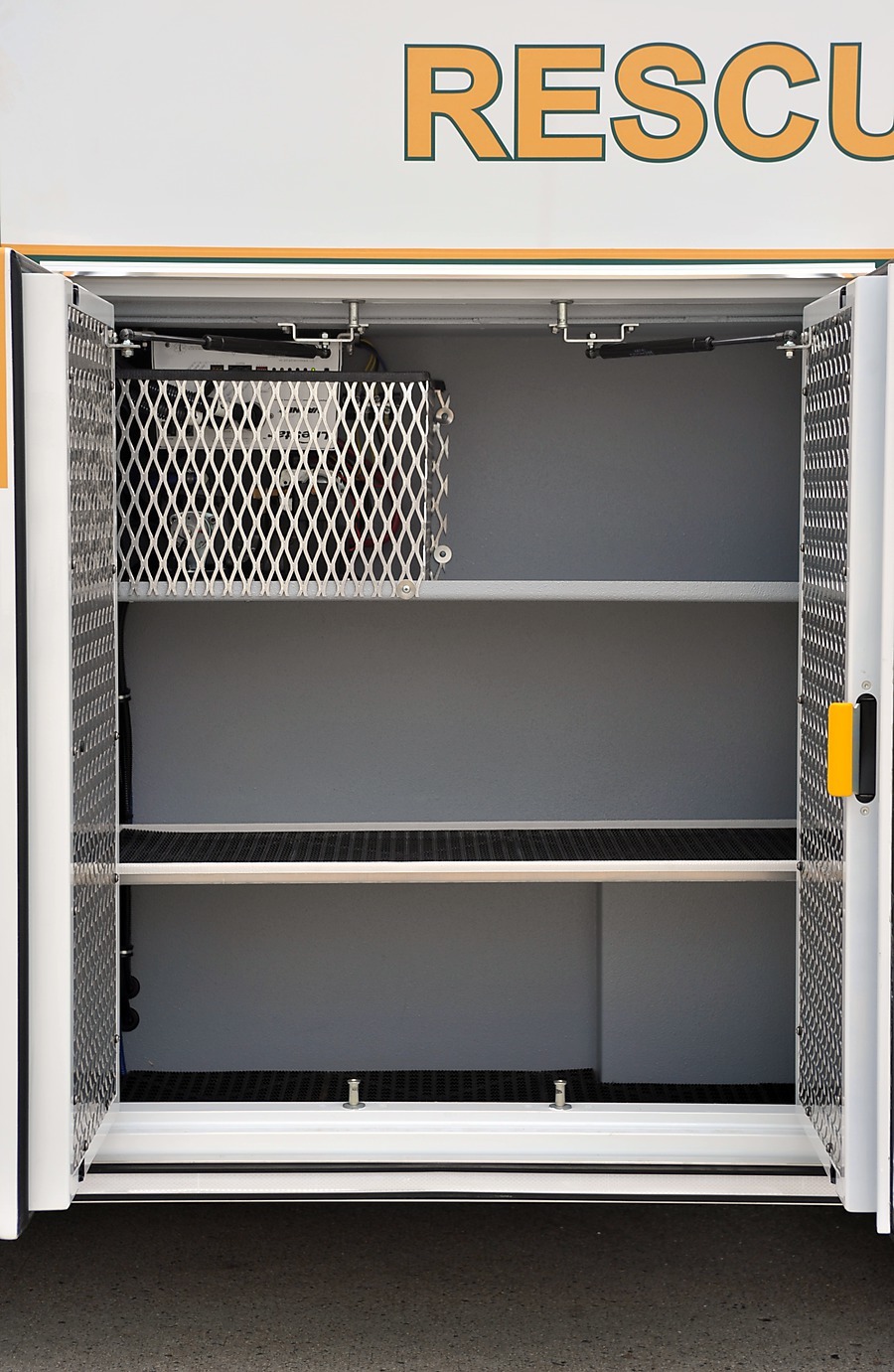
6.6.2 Detail
6.7 Exterior access to payload module right front cabinet
6.8 Shoreline inlet/indicator positioning
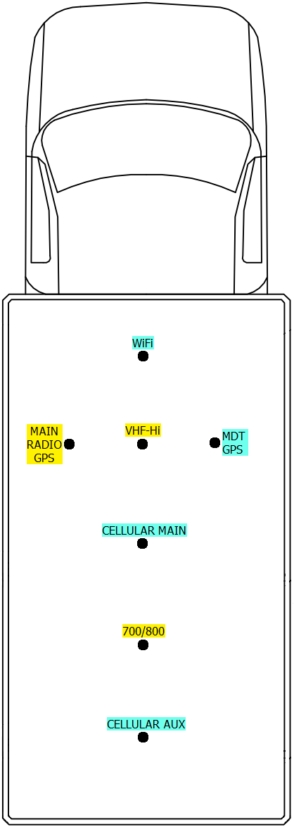
6.9 Exterior antennas
NOTE
The following diagram ONLY shows the number, nature, and rough placement pattern for required roof antennas. Nothing else in this diagram constitutes a requirement.
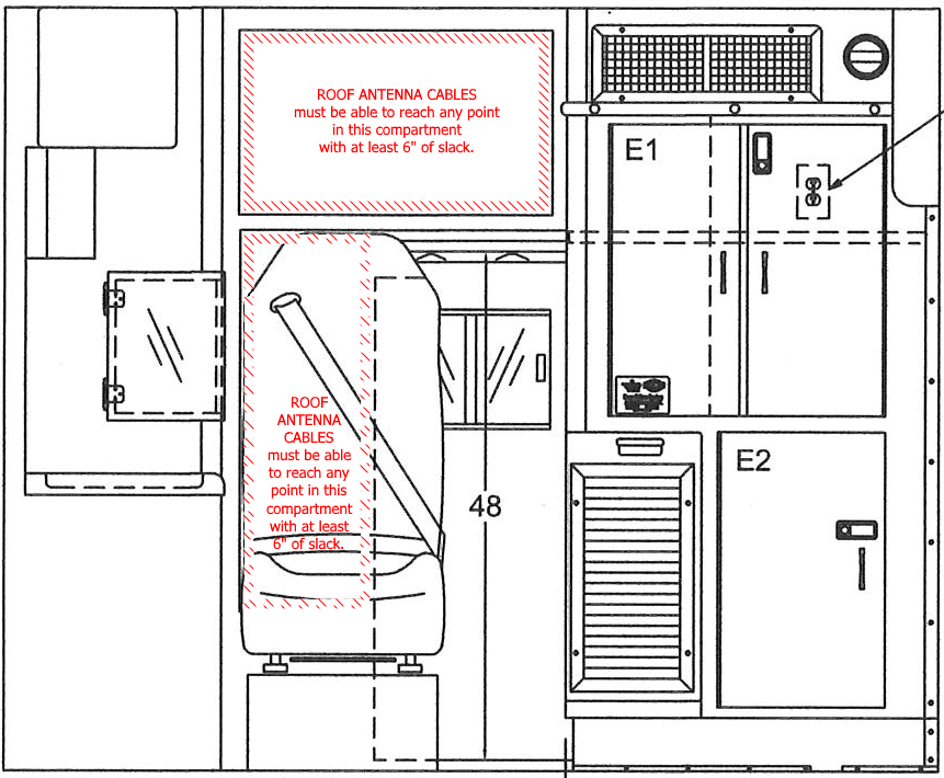
6.10 Cable termination points for exterior antennas
6.10.1 Bulkhead interior view
NOTE
The following diagram ONLY shows spaces into which exterior antenna cables should terminate. Nothing else in this diagram constitutes a requirement.
If you are viewing this diagram in black & white, the spaces of interest are the ones bordered by diagonal crosshatching.
If you are viewing this diagram in black & white, the spaces of interest are the ones bordered by diagonal crosshatching.
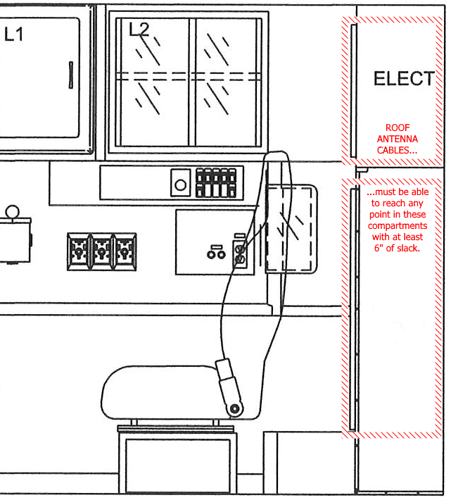
6.10.2 Left interior view
NOTE
The following diagram ONLY shows spaces into which exterior antenna cables should terminate. Nothing else in this diagram constitutes a requirement.
If you are viewing this diagram in black & white, the spaces of interest are the ones bordered by diagonal crosshatching.
If you are viewing this diagram in black & white, the spaces of interest are the ones bordered by diagonal crosshatching.
6.11 Communications/IT component mounting and power source chart